

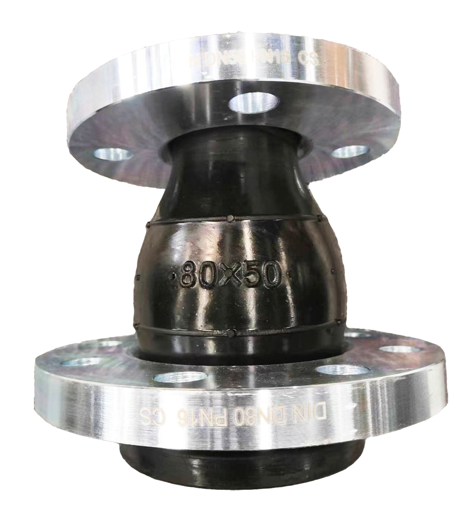
Rubber Reducer
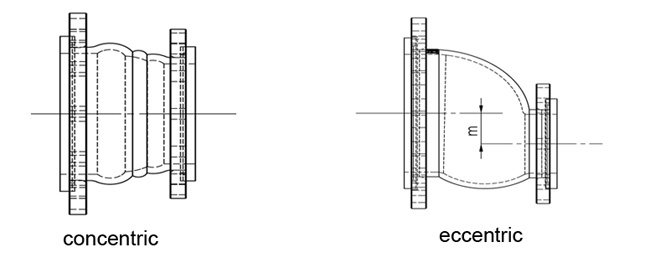
Rubber reducers, also known as reducing rubber joints/connectors, including concentric rubber reducers and eccentric rubber reducers, are special designed for piping systems to compensate more misalignment/offset, absorb pipe movements, relieve stress, reduce system noise/vibration, and to protect rotating mechanical equipment against start-up surge forces.
Features and Benefits
·Absorbs directional movement
·Absorbs vibration, noise and shock
·Compensates for more misalignment
·Wide flowing arch design
·Economical fully molded construction
·Special grooved flange ring design, prevent rubber end pulling out
·Solid galvanized steel floating flanges speed the installation time
·No gaskets required; integrally rubber flanged design
Looking for ideal Rubber Reducer Manufacturer & supplier ? We has a wide selection at great prices to help you get creative. All the Rubber Reducer Joint are quality guaranteed. We are China Origin Factory of Flexible Rubber Joint. If you have any question, please feel free to contact us.
Specifications
|
Nominal diameter:
|
DN25mm to DN3000mm
|
|
Maximum working pressure:
|
2.5 Mpa
|
|
Vacuum KPa(mmHg)
|
44.9(350)
|
|
Operating temperature:
|
-20℃-100℃
|
|
Corrosion resistance
|
Good
|
|
Applicable media
|
Sea water, drinking water, slurry, industrial sewage.
|
|
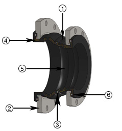
NO.
|
Components
|
Materials
|
Functions
|
 |
|
1
|
Rubber Bellows
|
EPDM/NR/NBR
|
Body
|
|
|
2
|
Ring Flange
|
Carbon Steel
|
Fasten
|
|
|
3
|
Steel Ring
|
Mild Steel
|
Reinforce
|
|
|
4
|
Tire Cord
|
Nylon
|
Reinforce
|
|
|
5
|
Arch Design
|
EPDM/NR/NBR
|
Reduce turbulence
|
|
|
6
|
Holding-on Design
|
/
|
Prevent Pulling Out
|
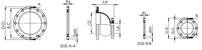
Concentric Data Sheet:
|
SIZE
|
LENGTH
|
MAX
|
VACUUM
|
Movement Capability(mm)
|
Prox.
|
||||
|
I.D×i.d.
|
F/F
|
Pressure
|
Rating
|
Comp.
|
Ext.
|
Lateral
|
Angular
|
Torsional
|
Weight
|
|
(mm)
|
(mm)
|
(bar)
|
(mm Hg)
|
(mm)
|
(mm)
|
(mm)
|
(degree)
|
(degree)
|
(kg)
|
|
40×25
|
160
|
20
|
500
|
25
|
16
|
45
|
35°
|
4
|
3
|
|
40×32
|
120
|
20
|
500
|
25
|
16
|
45
|
35°
|
4
|
3
|
|
50×32
|
180
|
20
|
500
|
25
|
16
|
45
|
35°
|
4
|
3
|
|
50×40
|
180
|
20
|
500
|
25
|
16
|
45
|
35°
|
4
|
3
|
|
65×40
|
180
|
20
|
500
|
25
|
16
|
45
|
35°
|
3.8
|
4
|
|
65×50
|
180
|
20
|
500
|
25
|
16
|
45
|
35°
|
3.8
|
4
|
|
80×40
|
180
|
20
|
450
|
30
|
20
|
45
|
35°
|
3.5
|
4
|
|
80×50
|
180
|
20
|
450
|
30
|
20
|
45
|
35°
|
3.5
|
4
|
|
80×65
|
180
|
20
|
450
|
30
|
20
|
45
|
35°
|
3.5
|
5
|
|
100×50
|
180
|
18
|
450
|
30
|
20
|
45
|
35°
|
3.4
|
5
|
|
100×65
|
180
|
18
|
450
|
30
|
20
|
45
|
35°
|
3.4
|
6
|
|
100×80
|
180
|
18
|
450
|
30
|
20
|
45
|
35°
|
3.2
|
6
|
|
125×65
|
180
|
18
|
400
|
30
|
20
|
45
|
35°
|
3.2
|
6
|
|
125×80
|
180
|
18
|
400
|
30
|
20
|
45
|
35°
|
3.2
|
7
|
|
125×100
|
200
|
18
|
400
|
30
|
20
|
45
|
35°
|
3.1
|
7
|
|
150×50
|
190
|
18
|
350
|
30
|
20
|
45
|
35°
|
3
|
7
|
|
150×65
|
200
|
18
|
350
|
30
|
20
|
45
|
35°
|
2.9
|
8
|
|
150×80
|
180
|
18
|
350
|
30
|
20
|
45
|
35°
|
2.8
|
8
|
|
150×100
|
200
|
16
|
350
|
30
|
20
|
45
|
35°
|
2.7
|
9
|
|
150×125
|
200
|
16
|
350
|
30
|
20
|
45
|
35°
|
2.6
|
9
|
|
200×100
|
200
|
16
|
350
|
30
|
22
|
40
|
35°
|
2.5
|
11
|
|
200×125
|
220
|
16
|
350
|
35
|
25
|
40
|
35°
|
2.4
|
12
|
|
200×150
|
200
|
16
|
350
|
30
|
22
|
40
|
35°
|
2.3
|
13
|
|
250×125
|
220
|
14
|
320
|
35
|
25
|
40
|
35°
|
2.2
|
16
|
|
250×150
|
220
|
14
|
320
|
35
|
25
|
40
|
35°
|
2.1
|
18
|
|
250×200
|
220
|
14
|
320
|
35
|
25
|
40
|
35°
|
2
|
20
|
|
300×150
|
220
|
14
|
320
|
35
|
25
|
40
|
35°
|
1.9
|
21
|
|
300×200
|
220
|
14
|
320
|
35
|
25
|
40
|
35°
|
1.8
|
22
|
|
300×250
|
220
|
14
|
320
|
35
|
25
|
40
|
35°
|
1.7
|
26
|
|
350×200
|
230
|
14
|
320
|
35
|
25
|
40
|
35°
|
1.6
|
29
|
|
350×250
|
230
|
14
|
300
|
35
|
25
|
40
|
35°
|
1.5
|
33
|
|
350×300
|
230
|
14
|
300
|
35
|
25
|
40
|
35°
|
1.4
|
36
|
|
400×200
|
230
|
12
|
300
|
35
|
25
|
40
|
35°
|
1.3
|
35
|
|
400×250
|
240
|
12
|
300
|
35
|
25
|
40
|
35°
|
1.2
|
39
|
|
400×300
|
240
|
12
|
300
|
35
|
25
|
40
|
35°
|
1
|
42
|
|
400×350
|
260
|
12
|
300
|
35
|
25
|
40
|
35°
|
1
|
49
|
|
450×300
|
240
|
12
|
300
|
38
|
25
|
35
|
35°
|
1
|
47
|
|
450×350
|
240
|
12
|
280
|
38
|
25
|
35
|
35°
|
1
|
54
|
|
450×400
|
240
|
12
|
280
|
38
|
25
|
35
|
35°
|
1
|
60
|
|
500×300
|
280
|
9
|
280
|
40
|
28
|
35
|
35°
|
1
|
60
|
|
500×350
|
240
|
9
|
280
|
40
|
28
|
35
|
35°
|
1
|
67
|
|
500×400
|
230
|
9
|
280
|
40
|
28
|
35
|
35°
|
1
|
73
|
|
500×450
|
240
|
9
|
280
|
40
|
28
|
35
|
35°
|
1
|
78
|
|
600×400
|
240
|
8
|
280
|
40
|
28
|
35
|
35°
|
1
|
94
|
|
600×500
|
240
|
8
|
280
|
40
|
28
|
35
|
35°
|
1
|
112
|
|
700×600
|
260
|
6
|
280
|
40
|
28
|
35
|
35°
|
1
|
132
|
|
SIZE
|
LENGTH
|
MAX
|
VACUUM
|
Movement Capability(mm)
|
Prox.
|
||||
|
I.D×i.d.
|
F/F
|
Pressure
|
Rating
|
Comp.
|
Ext.
|
Lateral
|
Angular
|
Torsional
|
Weight
|
|
(mm)
|
(mm)
|
(bar)
|
(mm Hg)
|
(mm)
|
(mm)
|
(mm)
|
(degree)
|
(degree)
|
(kg)
|
|
40×25
|
180
|
16
|
450
|
25
|
16
|
45
|
35
|
4
|
3
|
|
40×32
|
180
|
16
|
450
|
25
|
16
|
45
|
35
|
4
|
3
|
|
50×32
|
180
|
14
|
450
|
25
|
16
|
45
|
35
|
4
|
3
|
|
50×40
|
180
|
14
|
450
|
25
|
16
|
45
|
35
|
4
|
3
|
|
65×40
|
180
|
13
|
450
|
25
|
16
|
45
|
35
|
3.8
|
4
|
|
65×50
|
180
|
13
|
450
|
25
|
16
|
45
|
35
|
3.8
|
4
|
|
80×40
|
180
|
13
|
400
|
30
|
20
|
45
|
35
|
3.5
|
4
|
|
80×50
|
180
|
13
|
400
|
30
|
20
|
45
|
35
|
3.5
|
4
|
|
80×65
|
180
|
12
|
400
|
30
|
20
|
45
|
35
|
3.5
|
5
|
|
100×50
|
180
|
12
|
350
|
30
|
20
|
45
|
35
|
3.4
|
5
|
|
100×65
|
180
|
12
|
350
|
30
|
20
|
45
|
35
|
3.4
|
6
|
|
100×80
|
180
|
12
|
350
|
30
|
20
|
45
|
35
|
3.2
|
6
|
|
125×65
|
180
|
11
|
350
|
30
|
20
|
45
|
35
|
3.2
|
6
|
|
125×80
|
180
|
11
|
350
|
30
|
20
|
45
|
35
|
3.2
|
7
|
|
125×100
|
180
|
10
|
350
|
30
|
20
|
45
|
35
|
3.1
|
7
|
|
150×65
|
200
|
11
|
350
|
30
|
20
|
45
|
35
|
3
|
8
|
|
150×80
|
200
|
10
|
350
|
30
|
20
|
45
|
35
|
2.9
|
8
|
|
150×100
|
200
|
9
|
320
|
30
|
20
|
45
|
35
|
2.8
|
9
|
|
150×125
|
200
|
9
|
320
|
30
|
20
|
45
|
35
|
2.7
|
9
|
|
200×100
|
220
|
8
|
320
|
30
|
22
|
40
|
35
|
2.6
|
11
|
|
200×125
|
220
|
8
|
320
|
35
|
25
|
40
|
35
|
2.5
|
12
|
|
200×150
|
220
|
8
|
320
|
30
|
22
|
40
|
35
|
2.4
|
13
|
|
250×125
|
220
|
7
|
320
|
35
|
25
|
40
|
35
|
2.3
|
16
|
|
250×150
|
220
|
7
|
320
|
35
|
25
|
40
|
35
|
2.2
|
18
|
|
250×200
|
220
|
7
|
300
|
35
|
25
|
40
|
35
|
2.1
|
20
|
|
300×150
|
220
|
7
|
300
|
35
|
25
|
40
|
35
|
2
|
21
|
|
300×200
|
220
|
6
|
300
|
35
|
25
|
40
|
35
|
1.9
|
22
|
|
300×250
|
220
|
6
|
300
|
35
|
25
|
40
|
35
|
1.8
|
26
|
|
350×200
|
230
|
6
|
300
|
35
|
25
|
40
|
35
|
1.7
|
29
|
|
350×250
|
230
|
6
|
300
|
35
|
25
|
40
|
35
|
1.6
|
33
|
|
350×300
|
230
|
6
|
300
|
35
|
25
|
40
|
35
|
1.5
|
36
|
|
400×200
|
240
|
5
|
280
|
35
|
25
|
40
|
35
|
1.4
|
35
|
|
400×250
|
240
|
5
|
280
|
35
|
25
|
40
|
35
|
1.3
|
39
|
|
400×300
|
240
|
5
|
280
|
35
|
25
|
40
|
35
|
1.2
|
42
|
|
400×350
|
260
|
5
|
280
|
35
|
25
|
40
|
35
|
1
|
49
|
1. Pressure/Vacuum rating is based on neutral installed length(F/F).
2. Pressure rating is based on 30℃ operating temperature. The pressure rating is reduced at higher temperatures.
3. Weights in the above table are joints with DIN PN16 drilling retaining ring flanges.
4. Movements shown in the above table are non-concurrent.
5.Control units must be used when piping is not properly anchored.
6. Rated pressure in the above table is the maximum "working pressure". Test pressure is 1.5 times "working pressure", Burst pressure is 4 times " work pressure".
7. Normally, the flange drilling is based on DIN PN16, ANSI 150/250/300 lbs, BS PN10, JIS 10K are also available upon request.
- Previous:High Pressure Rubber Joint
- Rubber Joint: Double Sphere Type Next:
Contact us
Tel:
+86 18703845698
ailsa@gyldt.com